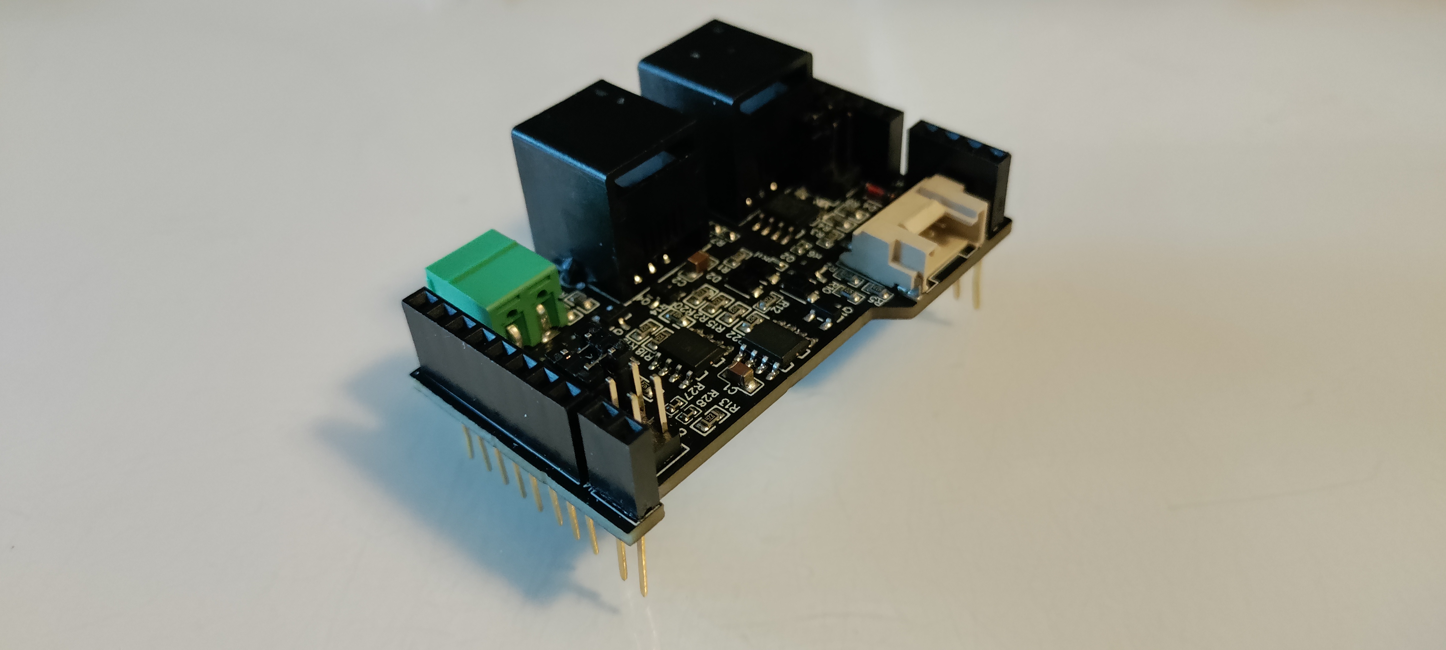
The DCC Interface provides an electrically isolated 5V copy of the DCC track signal. It can be used to feed the DCC information to a microcontroller for displaying the commands data or creating your own DCC decoder.
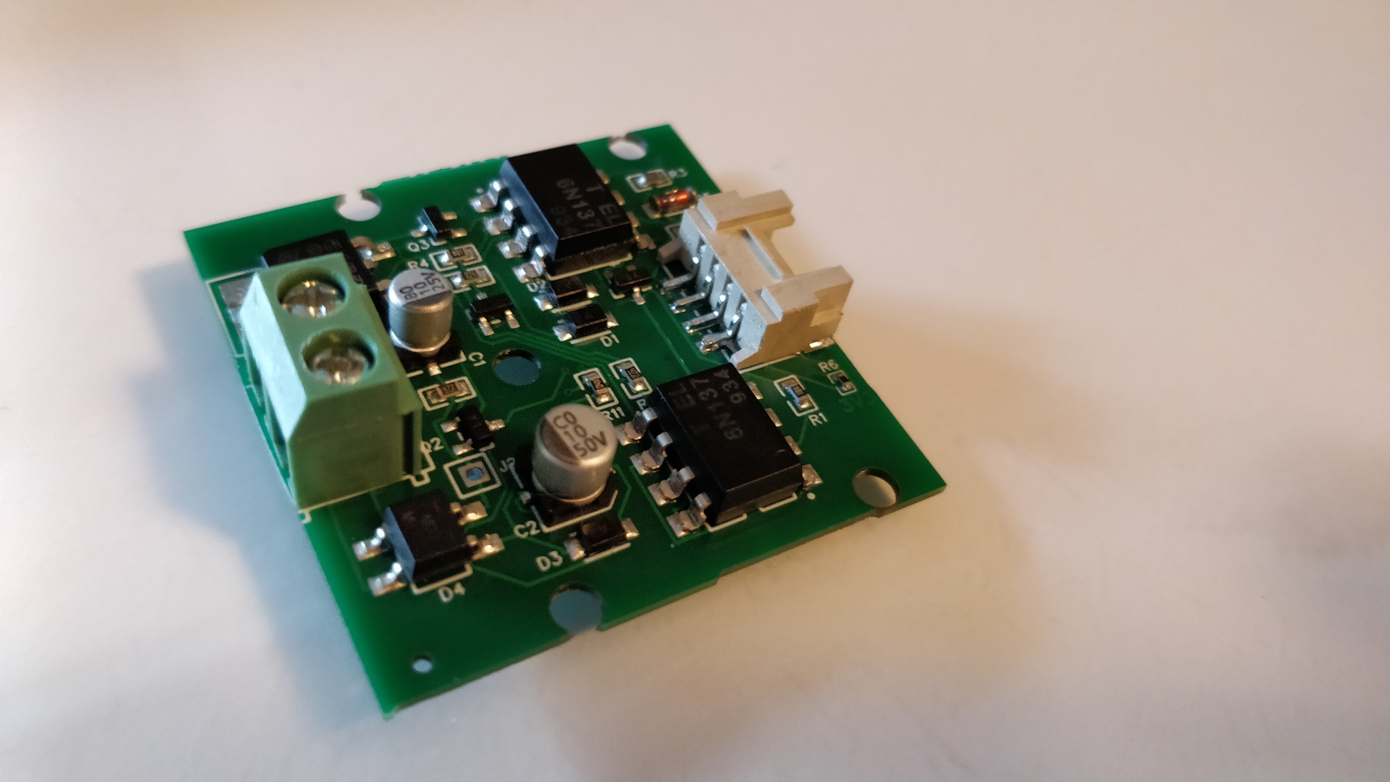
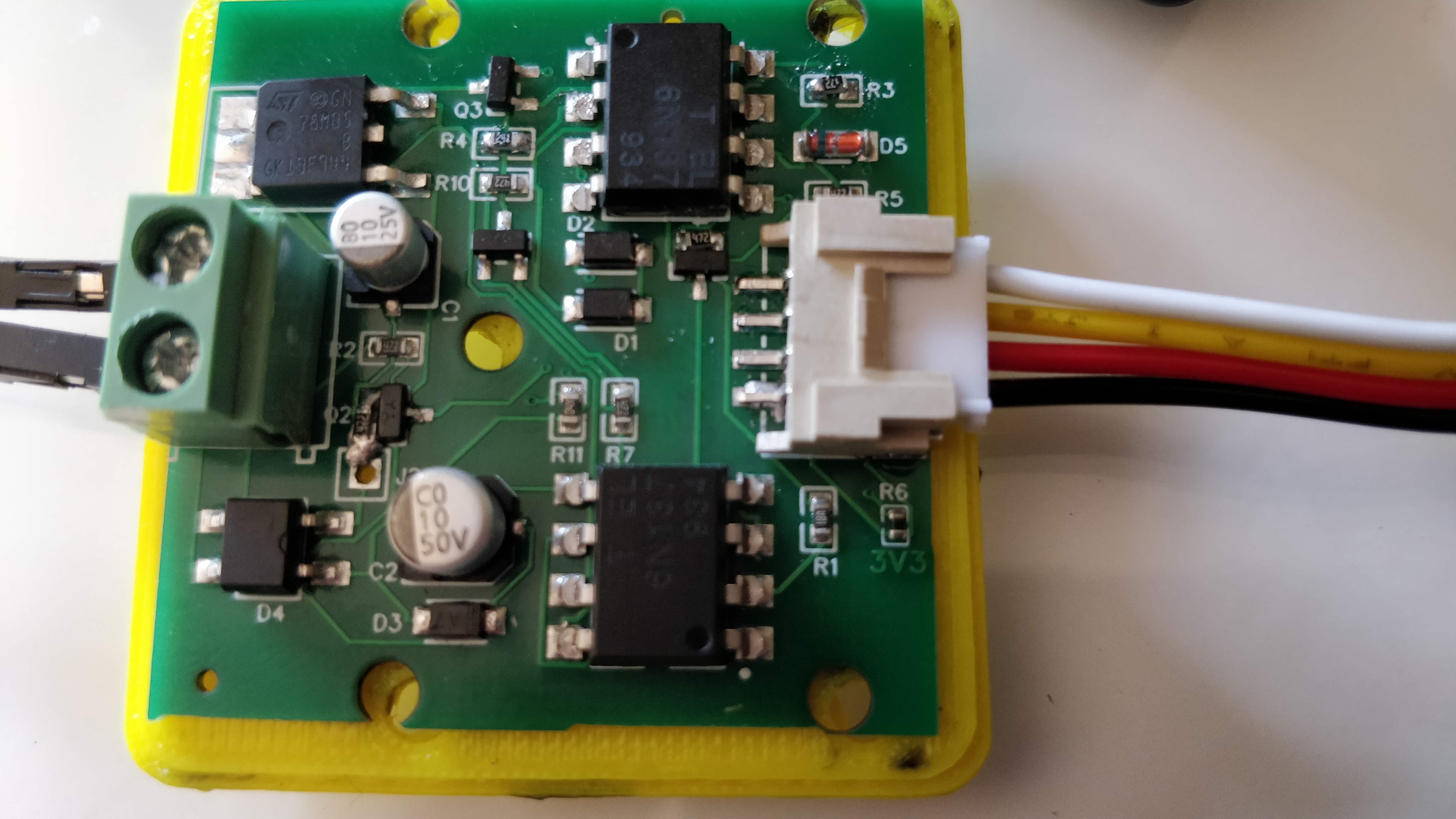
Schematics:
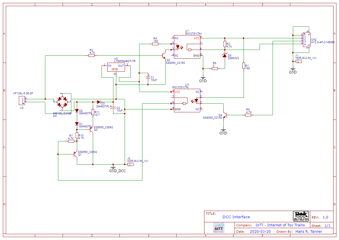
U4: DCC Input. Connect this to DCC Main or DCC Programming Track. DCC voltages in the range from 8 - 28V are supported, fits all common scale DCC voltages.
CN2: Grove Port. Use Grove port cable to connect to micro controller or solder connection wires to connector socket.
CN2 Pins:
- Pin 1: GND. Black wire on standard Grove cable.
- Pin 2: VCC. Red wire on standard Grove cable. Connect DC Voltage 3.3V - 5.5V
- Pin 3: ACK. Yellow wire on standard Grove cable. Activate this pin to send ACK pulse for Service Mode programming
- Pin 4: Tx. White wire on standard Grove cable. Connect to Rx pin on microcontroller to receive DCC signal. By default, the output voltage is limited to 3.3V by Zener diode D5. Remove R6 to allow output voltage to go up to VCC.
When using Arduino, install the Arduino DCC library and use it to communicate with the board.